Postion: Home > Our Case > Case Studies >
Sure, I'd be happy to provide a basic knowledge guide on customized sheet metal prototype manufacturing in China. As a Chinese manufacturer, we take pride in our professionalism and commitment to quality, as well as our ability to deliver on-time.
Customized sheet metal prototype manufacturing involves creating a preliminary version of a product using sheet metal as the primary material. This process allows for testing and refinement before moving on to full-scale production, saving time and money in the long run.
As a manufacturer, we offer a range of services to ensure that our customers receive the best possible results. This includes:
Design and engineering support: We can work with customers to design and engineer their sheet metal prototypes, ensuring that they meet all necessary requirements and specifications.
Material selection: We offer a range of sheet metal materials to choose from, including aluminum, stainless steel, and carbon steel, to ensure that the final product meets the required strength, durability, and aesthetic standards.
Precision manufacturing: We use advanced manufacturing techniques and equipment to ensure that our sheet metal prototypes are accurate and precise, and that they meet all required tolerances.
Finishing and assembly: We offer a range of finishing options, including powder coating and anodizing, as well as assembly services, to ensure that our customers receive a fully functional and finished product.
At our company, we are committed to delivering high-quality sheet metal prototypes on time and on budget. We understand the importance of getting products to market quickly, and we work closely with our customers to ensure that their prototypes are delivered when they need them.
If you're looking for a reliable and experienced Chinese manufacturer for your customized sheet metal prototype manufacturing needs, look no further than our company. Contact us today to learn more about our services and how we can help bring your products to life.
Customized sheet metal prototype manufacturing Chinese manufacturer: A Basic Knowledge Guide
Sheet metal fabrication is a versatile manufacturing process with an extensive list of techniques and usable metals. Getting familiar with the technology, how it works, and its applications will help you decide if it is the best option for your project. here's a comprehensive breakdown of this metal fabrication approach and its applications throughout numerous industries.
Overview of Sheet Metal Fabrication
Sheet metal fabrication is essential for various manufacturing processes, ranging from the manufacturing of toys to large-scale airplane parts. Notwithstanding its popularity, it is important to know how this manufacturing process works. Right hereŌĆÖs a detailed evaluate of sheet metal fabrication.
What is Sheet Metal Fabrication?
Sheet Metal Fabrication refers to the turning of flat metal sheets into metal products and structures. Typically, sheet metal processing methods involve transforming different types of sheet metals into parts and components. Therefore, it is helpful to think of this metal forming process not as a single manufacturing process but as a collection of forming techniques.
various Sheet Metal Fabrication techniques
These techniques often work in tandem with one another to produce the required part. The basic sheet metal fabrication techniques include cutting, bending, punching, stamping, welding, and finishing. We will dive into the details of these techniques shortly.
Sheet metal manufacturing is suitable for a range of metal materials. At Hongmingsheng, for instance, we produce sheet metal components made from Aluminum, Steel, Stainless Steel, Copper, and Brass. The manufacturing process is so common that you are unlikely to go about your day without encountering a sheet metal fabricated product. Whether itŌĆÖs a home appliance or smaller parts like brackets or enclosures, youŌĆÖll find these products everywhere.
A Guide to Sheet Metal Design Process
Many people tend not to understand the basic steps involved in the sheet metal manufacturing process. The absence of fundamental knowledge can make it difficult to have realistic requirements and expectations for a project. The sheet metal processing methods often involve a multi-step process, requiring several skilled experts and tools for successful job completion.The Idea
Every rapid prototyping process begins with an idea, and sheet metal design is no exception. It begins with basic concepts of what you want as a designer. You can put these ideas down roughly to provide realistic requirements for your project. It may also involve the designing of a 3D model of the desired sheet metal component. The version often includes requirements for wall thickness, bend radii, hole orientation, bend allowance, and greater.
Creating Engineering Drawings
After the completion of a 3D model, there is a need to create drawings for manufacturing. Before any work can begin, engineers need to develop blueprints. These blueprints will determine the specifications of the sheet metal needed to make initial drawings.
The drawings are what will be sent to the machine shop. The drawings often include all manufacturing information such as material selection, surface finishing, and more.
Manufacturability Analysis
Along with other related calculations, the drawings will be rechecked to ensure they follow requirements and specifications. Following a DfM strategy helps to focus on simplifying the designs and possible reduction of part counts. Such analysis suggests standardizing parts for various applications.
Furthermore, engineers will get insights into developing designs that can be easily manufactured. Once the manufacturability analysis is complete, there will be a final shop drawing with in-depth calculations of stress/strain levels and load limitations. The information available therein will determine the sheet metal fabrication process.
Prototype Development
Once there is a sheet metal design model, engineers carry out several processes to maintain the componentŌĆÖs geometry. These methods include cutting, bending, punching, stamping, and welding. Surface finishes also help to improve the aesthetics of the created prototype. It is important to carry out these steps one after the other. Rushing through the process or skipping one step may compromise the quality and integrity of the final product.
Prototype Testing
After developing the prototype, clients then evaluate the prototype to ensure that it meets their requirements. The testing may also involve using such components in real-life conditions. Also, evaluation can be done with users giving feedback on the products.
Full-Scale Production
A prototype that passes testing and meets the specified specification will go into full element production.
Types of Metal Fabrication Processes
To understand the formation of different parts using sheet metal fabrication, it is imperative to know the different types of techniques used. These sheet metal processing methods help to transform flat sheets of metal into three-dimensional, functional components. Below are the most common sheet metal processing techniques.1. Laser Cutting Service
CAD/CAM and engineering capabilities, and machines equipped with automation. We can meet tolerances to ┬▒0.15mm.
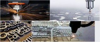
Water-jet cutter is able to cut material without interfering with the material's inherent structure as there is no 'heat affected zone' or HAZ, this allows metals to be cut without harming or changing their intrinsic proerties.

3. Plasma Cutting Service
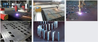

Contact us or email to our sales team directly for your project info@hms1688.com
There are basically only three components to sheet metal stampingŌĆöthe sheet metal, die, and press machineŌĆöbut any single part can require multiple steps to arrive at its final form. The following guide explains a few common processes that might occur during metal stamping.
Metal Bending
To ensure a hitch-free bend and to avoid deformation, the following 10 tips are vital when designing.
1. Part thickness
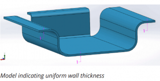
Parts must have a uniform wall thickness throughout. Xometry Europe is capable of manufacturing bent sheet metal parts up to 6.35mm in thickness, but this tolerance mainly depends on the geometry
2. Hole and slot clearance
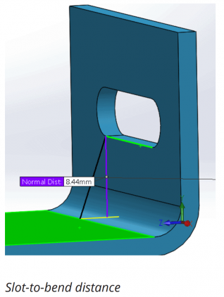
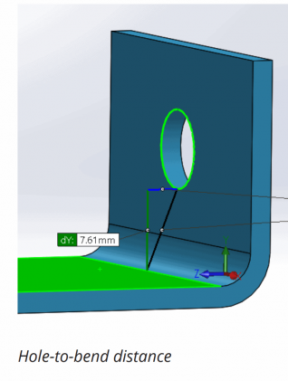
The distance of holes from the bend should be at least 2.5x the material thickness. Slots require more clearance. Slots should be placed at a distance of at least 4x the material thickness from the bend edges. This is because holes and slots are likely to deform when placed near a bend. Also, to avoid a bulging effect, place these features at a distance of at least 2x the material thickness from part edges.
3. Bend radius
The radius of bends must be a minimum of 1x the material thickness to prevent parts from fracturing or distorting. Also, the Bend radius should be kept consistent to minimize cost.
All bends in the same plane should be designed in one direction to prevent part reorientation. This saves both money and time.
Large, thick parts should not have small bends due to the high tendency to become inaccurate. As a rule of thumb, the inside bend radius should at least equal to the material thickness.
4. Curls
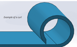
The outside radius of curls must be at least twice the material thickness.
In addition, the distance of holes from curls should be at least equal to the curl radius plus the material thickness. Other bends should be placed away from the curl at a distance of at least 6x the material thickness plus the curl radius.
5. Clearance for countersink
Countersinks on sheet metal parts are usually produced with hand tools. They must not be deeper than 0.6x the material thickness. This means that the maximum depth of a countersink in a 10 mm thick material should be 6 mm.
Furthermore, countersinks must have a minimum distance of 3x the material thickness from a bend, 4x from an edge, and 8x from each other.
6. Hems
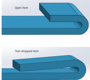
Hems are folds created at the edge of parts to create a safe, rounded edge. There are three hem designs with different design rules.
For open hems, the minimum inside diameter should be at least equal to the material thickness, as larger diameters will cause loss of circularity. To ensure a perfect bend, the return length should be 4x the material thickness.
Teardrop hems should also have a minimum inside diameter that is equal to the material thickness. The opening should be a minimum of ┬╝x the material thickness, while the run length should be at least 4x the material thickness following the radius.
7. Chamfered sides
Chamfers on flanges must leave enough room for bends to avoid deformed parts.
8. Bends next to each other
Successive bends should be avoided except when absolutely necessary. A common problem for successive bends is the difficulty to fit the already bent parts on the die. However, when unavoidable, the intermediate part should be longer than the flanges.
9. Clearance for notches and tabs
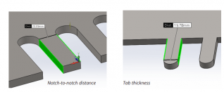
The notch to bend distance should be at least 3x the material thickness plus the radius of the bend. Tabs, on the other hand, must be 1 mm or the material thickness away from each other, whichever value is greatest.
10. Relief cuts
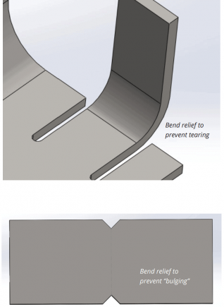
Relief cuts are essential in avoiding bulging and tearing at bends. The width of the relief cuts should at least be equal to the material thickness, and the length should be longer than the radius of the bend.
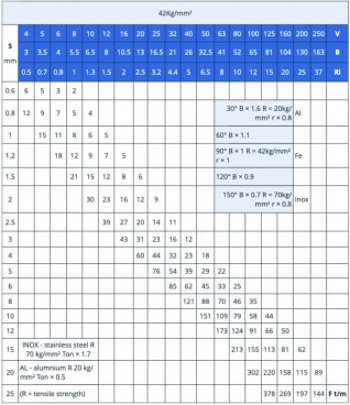
Calculating Required Bending Force
Different factors are involved in creating the right bend in a workpiece. These include:
- Bending strength of the material
- Degree of bending
- Thickness of the workpiece
- Bend angle
- Internal radius
- Vee die opening
- Minimum internal edge
- S (mm) ŌĆō Thickness of the workpiece
- V (mm) ŌĆō Vee die opening
- B (mm) ŌĆō Minimum internal edge
- Ri (mm) ŌĆō Internal radius
We welcome all welding metal fabrication orders, from smal, single part orders to large assemblies and multiple run parts. Whether it is just few pieces or it is a full container, we take the responsibility.
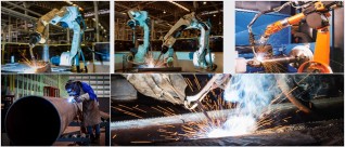
Our welding services include 5 robotic welders along with mutiple welding stations, and 5 multiple axis positioners as well as on-site experienced welding inspector.
We invest in our customers by investing in our equipment and craftsmen. Our capabilities and main equipment include:
1. Robotic Welder
├ś5 sets CNC robotic welders
├śMultiple axis positioners
├śTouch-sensing & seam-tracking
├śAluminum, carbon steel, and stainless steel capable
Contact us or email to our sales team directly for your project info@hms1688.com
2. Mig Welding (GMAW & FCAW)
3. Tig Welding (GTAW)
4. Stick Welding (SMAW)
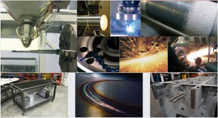
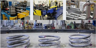
5. Pipe Bending
6. Secondary Services
1. Heat treatment to adjust metal physical and chemical properties;
2. Surface treatment: Painting, Powder coating, Zinc plating, Nick plating, Anodizing, Galvanizing, Polishing, etc...
3. Assembly;
4. Customized packaging, oil protection as per needed.